# Model tab
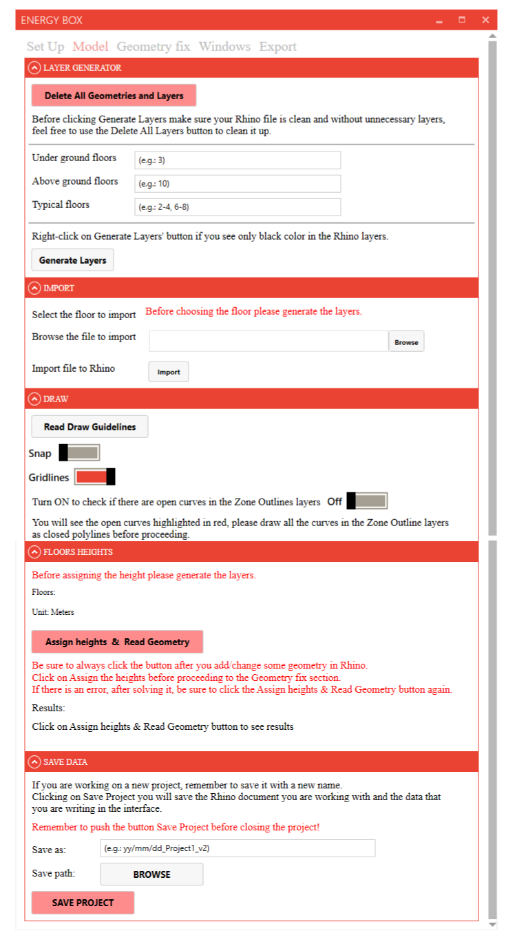
# Layer Generator section
# Delete all geometries and layers
Warning:
If you are continuing to work on an existing model, do not use this button!
Before initiating the layer generation process for a new model by clicking Generate Layers, ensure that your Rhino file is free of unnecessary layers.
To achieve this, it is recommended to click on Delete All Geometries and Layers, thereby removing any superfluous layers that may have been automatically generated by default in Rhino.
# Floors setup
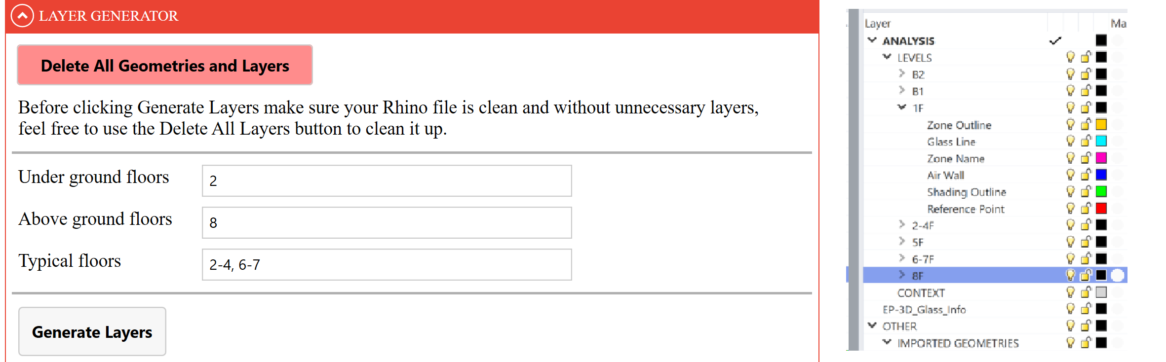
The number of Under ground, Above ground, and Typical floors are essential to the functionality of EnergyBox.
Follow the instructions below to correctly enter data into the respective fields:
- Under ground floors: Enter the number of floors located below ground level (e.g., 1). Use 0 if there are no underground floors.
- Above ground floors: Specify the number of floors situated above ground level (e.g., 2). The ground floor is designated as 1.
- Typical floors: Indicate a range for floors with identical plans and glazing settings, in the format 'xx-xx' (e.g., 2-3). Use 0 if there are no typical floors.
Once the desired inputs have been provided press Generate Layers. This will create the corresponding number of layers in the Rhino Layer Manager, which forms the basis for your 2D modeling.
If adjustments to these layers are necessary, the most straightforward approach is to press Delete All Geometries and Layers. Afterward, recreate the required layer as needed.
Tip:
EnergyBox follows a specific convention for naming floors. The ground floor will be referred to as "Level 1F", while underground levels will have the prefix "B" (e.g.: the first underground level will be labeled as "Level B1").
In case the interface is not functioning as anticipated, refer to the instructions that will appear on the right side of the Generate Layers button, they should fix the problem.
# Import section
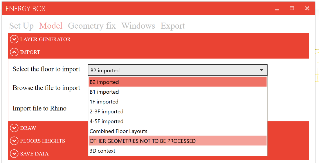
In the Import section you have the option of importing underlays that will be sorted into easily manageable layers in the Rhino Layer Manager. You can import a reference for:
- Each floor;
- Combined Floor Layouts, in the case where you have a file containing all floors together.
- Other geometries or 3D contexts, in case you need an additional reference when drawing.
Select the floor you wish to import from the drop-down menu, find the file by clicking Browse and then click on Import. (The drop down list is populated after the layers have been generated.)
It is possible to import .dwg, .pdf, or .3dm files.
Tip:
Here (opens new window) you can find an example that you can use to test the Import function. The file contains all floors of the building, so you have to import it by selecting the option "Combined Floor Layouts" from the drop-down menu.
# Draw Section
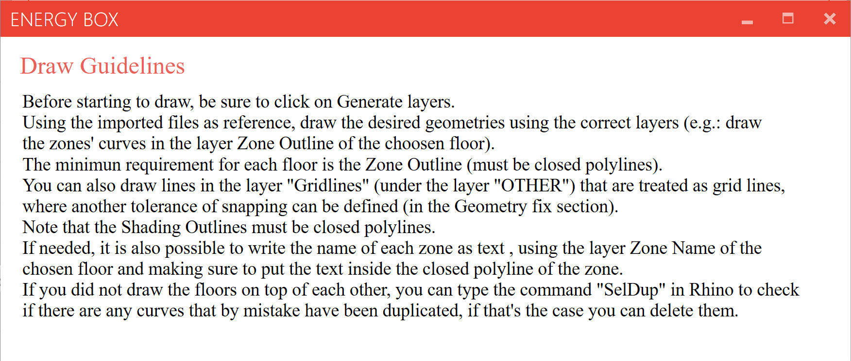
The main input of EnergyBox are the 2D lines, which must be drawn in the correct layer. The Read Draw Guidelines provides a convenient summary of the most important points.
Tip:
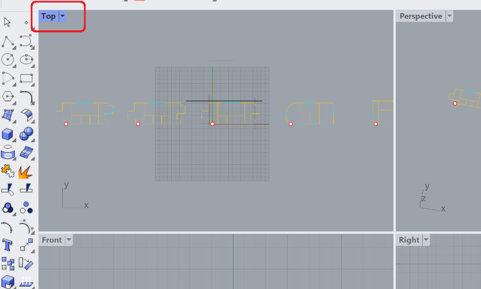
It is recommended to draw using the Top View in Rhino, which can be activated by simply double-clicking on the "Top" located at the top left of the 4 viewports that are present by default within Rhino. You can return to the 4 viewports simply by double-clicking on the "Top" label again.
# Key facts to note:
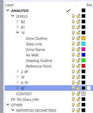
Zone Outline: The minimum input for an energy model. All inputs must be closed polylines.
At the end of the drawing phase, it is possible to check whether there are any open curves in the Zone Outline layers, by activating the dedicated toggle in the Drawing section. The highlighted (in red) lines should be deleted to avoid errors.
Zone Name (optional): A text field positioned within the bounds of the zone outline.
Glass Line (optional): A line that defines the size of the glazing on the wall.
Air Wall: Any internal virtual partitions that are required. These are unclosed polyline that fit within large Zone Outlines.
Shading Outline (optional): Horizontal shading projection above windows, which must also be closed polylines.
Reference Point: When different floors are not drawn "on top of" each other, reference points can be used to align the model vertically as desired.
If the floors are not drawn "on top of" each other, use the "SelDup" command in Rhino to check if there are any curves that have been duplicated by mistake. Any duplicates should be deleted.
There are two typical ways of creating and allocating this geometry:
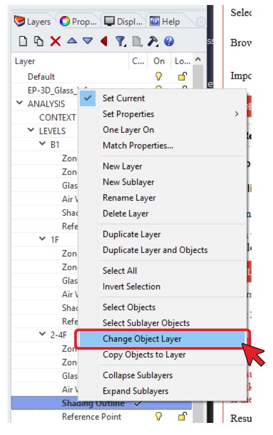
Allocating layers to pre-existing 2D lines
In this method, EnergyBox-compatible geometries have already been created in CAD or Rhino and the 2D lines are simply reassigned to the appropriate layer in Rhino's Layer Manager using the 'Change Object Layer' functionality:
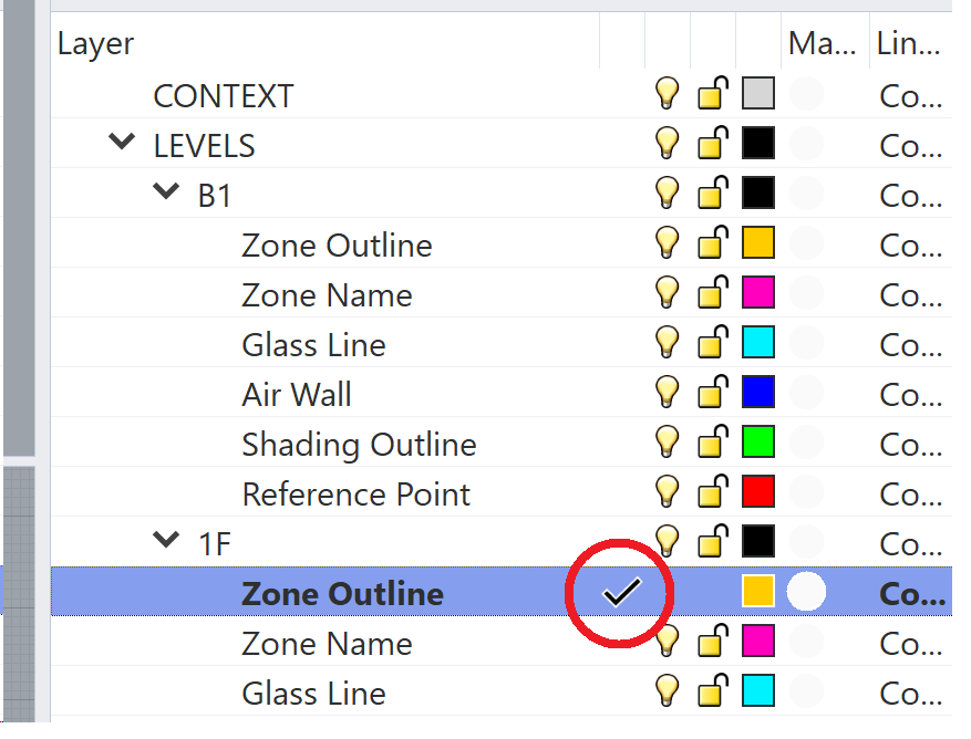
Creating 2D lines on the correct layers
In this method, first the correct layer is selected, making it active, and then the 2D lines are drawn. This is often done using some 2D underlay for reference, either snapping to the underlay or using a drawing grid.
To be sure you are drawing in the correct layer make sure the tick is present at the side of the name of the desired layer, if it is not there you can simply double click at the side of the name to make that layer the active one.
# Visibility of Imported Geometry function:
By activating or deactivating the 'Visibility of Imported Geometry' toggle, it is possible to display or not display the imported geometry to facilitate the drawing of 2D lines.
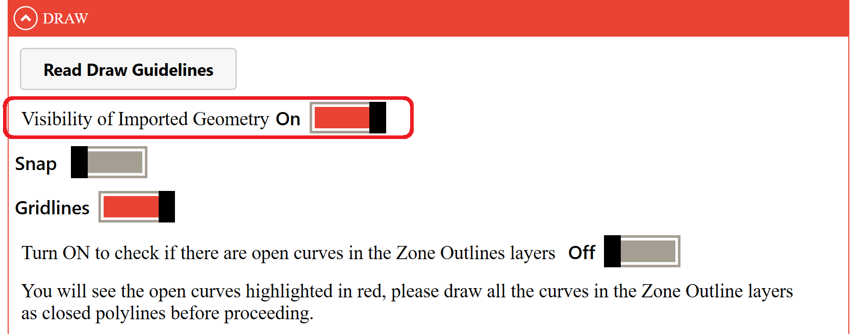
For drawing assistance there are 2 options within EnergyBox: "Snap" and "Gridline":
Tracing underlays with Snap
When this setting is activated, you will see these components activated at the bottom of the Rhino interface:

Using this option, the mouse cursor will automatically snap to the near geometry, that for example could be an end point of another curve or the intersection point of other curves.
Tracing underlays with Gridline
When this setting is activated, Rhino's gridlines and the Ortho function will be activated.
This function limits the drawing possibilities, only allowing the drawing of perfectly vertical or horizontal lines, which can be useful if your building has this type of geometry.
Advanced functionality
Lines can also be drawn in the layer "Gridlines" layer (under the layer "OTHER"). These geometries are treated as grid lines, where another tolerance of snapping can be defined (in the Geometry Fix section). Gridlines must be drawn with respect to a specific floor, meaning they will then be moved by the reference point.
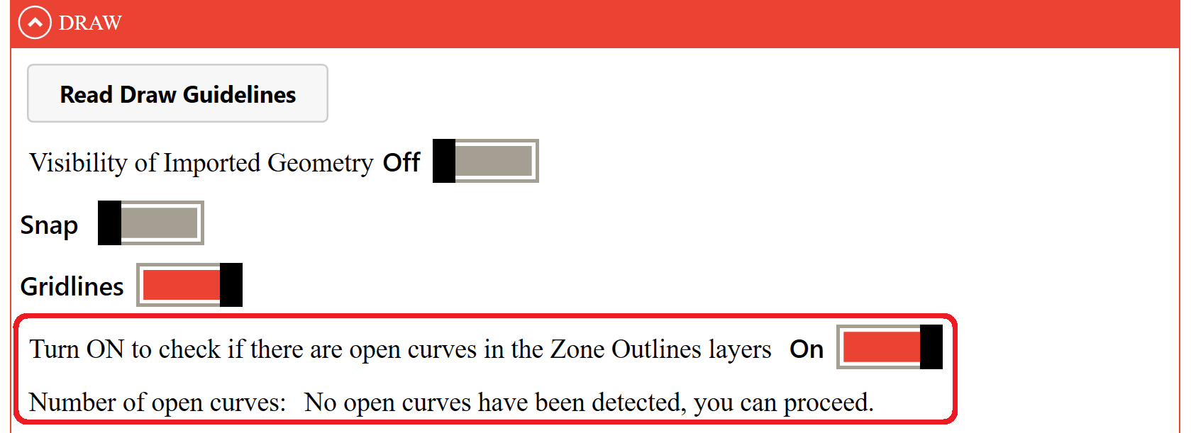
# Automatic Zone Outlines Check for Open Curves
By activating this toggle, it is possible to analyse all the curves in the project and check whether any curves in the Zone Outlines were left open by mistake.
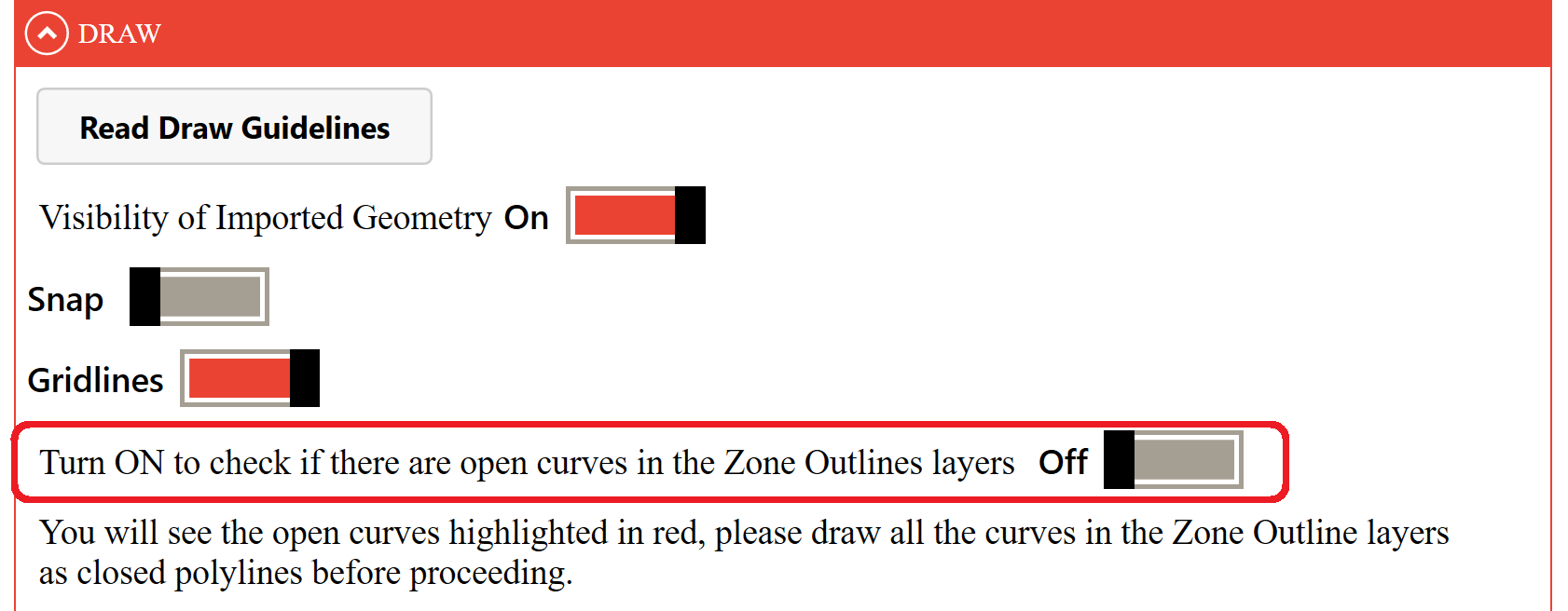
If there are any open curves, the interface will indicate how many there are and highlight them in red.
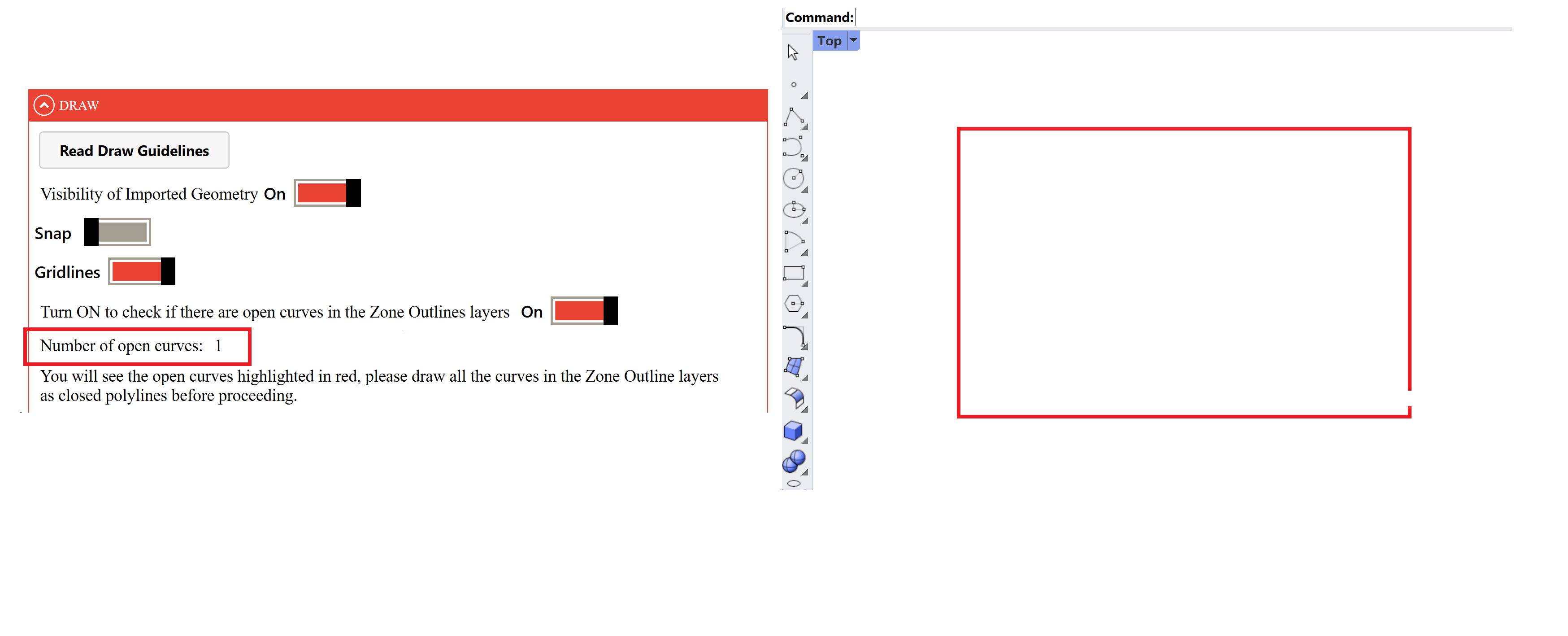
Simply deactivate the toggle, close any curves that are still open, and do another check to be sure that all Zone Outlines curves are closed before proceeding.
# Floor Heights section
In this section, the heights of all floor must be entered in metres. Once the data have been entered, press Assign Heights & Read Geometry.
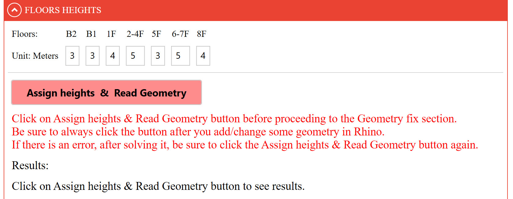
Directly below, feedback is provided in the Results field. If there are any errors, such as open curves that you have not previously eliminated or floors that do not contain any geometry, the interface will report that in the floors containing errors the geometries have NOT been registered.
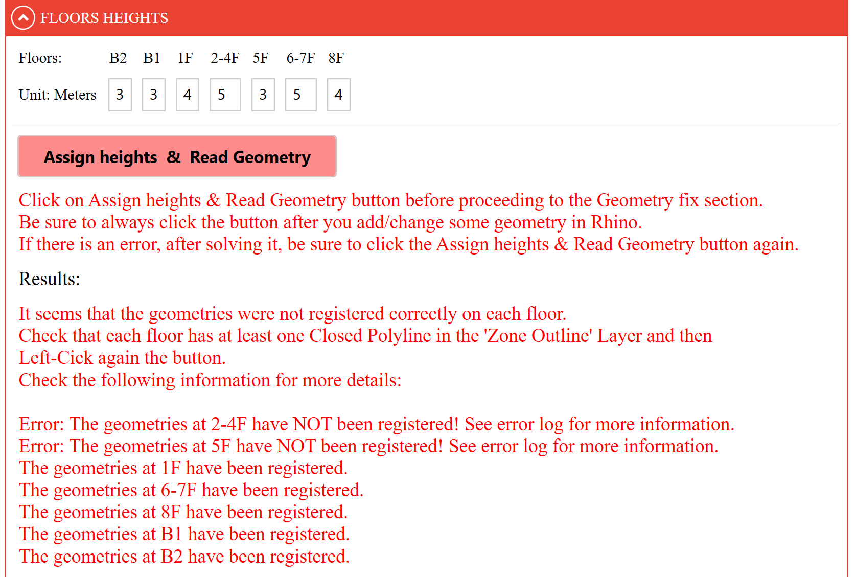
Make sure to correct all geometries on the floors that have not been registered correctly and click the Assign Heights & Read Geometry button again until you see that geometries have been registered in all floors.
You can use the Automatic Zone Outlines Check for Open Curves function provided in the Draw section to check that the Zone Outlines curves are all closed.
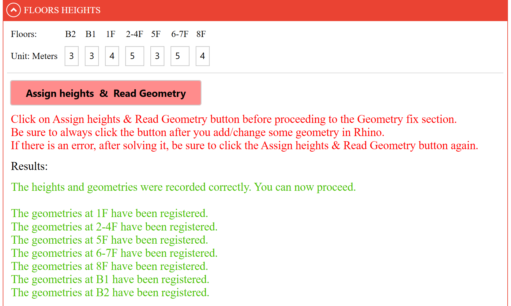
Tip:
If the interface is not performing as expected, consult the instructions displayed in the Results field. These instructions should address the issue.
# Save Data section
At this point the current EnergyBox inputs can (optionally) be saved as a .JSON file using the SAVE PROJECT button
This function saves both the data within the EnergyBox interface and the Rhino file, so that both a .JSON file and a Rhino file will be located in the chosen path with the chosen name.
To continue working on the project in the future:
- Re-open the Rhino file you have just saved with the SAVE PROJECT button (e.g.: 2023.03.07_Project1_v1.3dm).
- Launch the EnergyBox interface via Rhino (as already explained in the Set Up section).
- Import the
.JSONfile containing the interface data (e.g.: 2023.03.07_Project1_v1.json), using the Import button present in the Import Data section, within the Set Up tab.